

 Duyen Nguyen
Any industrial milling machine, from traditional mechanical mills to modern CNC mills, cannot operate without its “central nervous system”—the electrical circuit. Understanding the electrical circuit of a milling machine not only ensures efficient operation but also serves as the key to quickly diagnosing and resolving issues, saving both time and costs.
This article provides a comprehensive A-Z overview of this critical system, covering its structure, principles, how to read schematics, and the most common faults.
1. What is the Electrical Circuit of a Milling Machine? Its Importance in Operation
The electrical circuit of a milling machine is a complex system comprising interconnected electrical components and wiring arranged according to a specific schematic. Its primary function is to receive, process, and distribute electrical energy to control all operations of the milling machine.
Importance of the Electrical Circuit:
- Precise Control: Determines the spindle speed, direction, and movement speed of the X, Y, Z axes, ensuring the machined product aligns with the design.
- Power Supply: Acts as the lifeline, delivering energy to motors, coolant pumps, and auxiliary systems.
- Safety Assurance: Integrates protective mechanisms (thermal relays, circuit breakers, emergency stop buttons) to disconnect the circuit promptly during overloads or short circuits, ensuring safety for operators and equipment.
- Signal Transmission: Serves as the interface between the operator (via buttons or CNC interface) and the machine’s mechanical components.
A stable electrical circuit is the foundation for a milling machine’s reliable and durable performance.

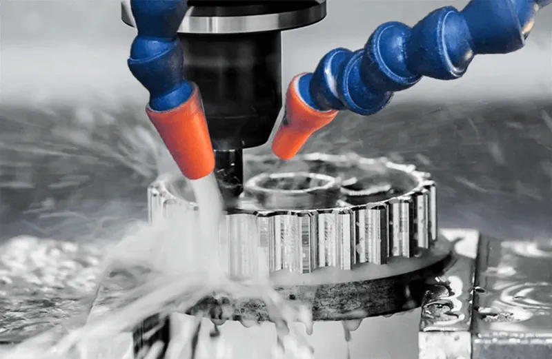
A CNC milling machine in operation, illustrating the role and importance of a stable electrical circuit.
2. Basic Structure of an Industrial Milling Machine’s Electrical Circuit
Despite variations among milling machines, their electrical circuits typically consist of four main components housed within the control cabinet.
2.1. Central Control Cabinet
This is the hub for the system’s core components, including critical switching, protection, and control devices:
- Main Circuit Breaker (CB): A device for switching on/off the machine’s total power supply and protecting against short circuits or overloads.
- Contactor: Used to switch high-power circuits, such as supplying power to the spindle motor.
- Thermal Relay: Paired with the contactor to protect motors from overload. If the motor current exceeds safe levels, the relay disconnects the control circuit.
- PLC/CNC Controller: In CNC milling machines, this is the central processor, receiving command codes (G-code, M-code) and outputting precise control signals to various components.
- Variable Frequency Drive (VFD): Adjusts the spindle motor speed flexibly.
2.2. Power Circuit
This circuit is responsible for supplying high-power electricity directly to the motors. It includes large cross-section wires and high-capacity electrical devices (contactors, circuit breakers) to power:
- Spindle motor.
- Motors for X, Y, Z axes (typically servo or stepper motors in CNC machines).
- Coolant pump.

Main components of the power circuit in an industrial milling machine
2.3. Control Circuit
The control circuit operates at low voltage (typically 24V DC) to handle signal reception and processing. It receives commands from user inputs (buttons, switches, CNC interface) and feedback signals from sensors, then activates contactors in the power circuit.
2.4. Peripheral Devices and Sensors
These are the system’s “sensory organs” and “actuators,” including:
- Input Devices: Push buttons (Start, Stop, E-Stop), rotary switches, knobs, etc.
- Output Devices: Status indicator lights, alarms, etc.
- Sensors: Limit switches (restricting axis movement), proximity sensors, encoders (measuring and feeding back motor position and speed).
3. Operating Principle of the Milling Machine’s Electrical Circuit
The operation of the electrical circuit can be summarized in five simple steps:
- Power Supply: When the main circuit breaker is turned on, three-phase power (typically 380V) is supplied to the control cabinet. A switching power supply converts the voltage to 24V for the control circuit.
- Command Input: The operator presses the “Start” button or runs a G-code program on the CNC interface.
- Signal Processing: The control circuit (or CNC controller) receives and processes the signal logically.
- Power Circuit Activation: The control circuit sends a low-current signal to the coil of the corresponding contactor. The contactor closes, allowing high-power current from the power circuit to flow to the spindle motor or axis motors.
- Feedback: The motors begin rotating. Encoders attached to the motors count rotations and send feedback to the CNC controller to ensure the motors operate at the programmed speed and position. This control-feedback loop enables real-time, stable, and accurate operation.
4. Guide to Reading Milling Machine Electrical Schematics

Block diagram illustrating the operating principle of a milling machine’s electrical circuit.
Electrical schematics are essential for maintenance and troubleshooting. Mastering their interpretation allows for quick issue identification.
4.1. Schematic for Mechanical Milling Machines
Schematics for mechanical mills are relatively simple, primarily showing connections between basic electrical components like push buttons, relays, contactors, and thermal relays. The schematic typically distinguishes between the power circuit (bold lines) and the control circuit (thin lines).
4.2. Schematic for CNC Milling Machines
CNC schematics are significantly more complex. Instead of simple relay logic, they depict connections between the CNC controller and other components, such as:
- Servo/Stepper Drivers: Signal amplifiers for controlling axis motors.
- Variable Frequency Drive (VFD): An intermediary between the controller and the spindle motor, responsible for speed regulation.
- I/O Modules: Manage signals from numerous sensors and buttons.
- Block Diagrams: Often used to provide an overview of signal flow rather than detailing every wire connection.
5. Common Electrical Circuit Faults in Milling Machines and Solutions
Below are the most frequent electrical issues and basic troubleshooting steps.
5.1. Power Loss or Voltage Drop
Symptoms: The machine fails to power on, the CNC screen is blank, or indicator lights are off.
Causes & Solutions:
- Check the status of the main circuit breaker (in the cabinet and at the facility) to see if it has tripped.
- Inspect fuses in the control circuit.
- Ensure the 24V switching power supply is operational and providing sufficient voltage.
- Tighten any loose wire connections.

Checking the 24V power supply, a critical step in troubleshooting power loss issues
5.2. Spindle Motor Fails to Rotate or Rotates Weakly
Symptoms: Pressing the start button does not activate the spindle, or it rotates weakly and stops when cutting begins.
Causes & Solutions:
- Mechanical Machines: Check if the contactor supplying the motor is engaging and if the thermal relay has tripped.
- CNC Machines: Verify if the VFD displays errors (e.g., overload, overvoltage). Reset the VFD and check if M3/M4 commands in the program are correct.
- Inspect the drive belt and related mechanical components.
5.3. X, Y, Z Axes Fail to Move or Move Incorrectly
Symptoms: The machine does not respond to movement commands, moves jerkily, or the CNC screen displays errors like “Servo Alarm” or “Following Error.”
Causes & Solutions:
- Check if the emergency stop button is engaged.
- Verify if the machine has reached a travel limit (triggering a limit switch).
- Inspect the corresponding axis driver for error indicators. Try restarting the machine.
- The issue may stem from the servo motor, encoder, or mechanical jams.
6. Safety Precautions for Inspecting and Repairing Milling Machine Electrical Circuits
Working with industrial electrical systems is inherently dangerous. Adhere to these core safety principles:
- Complete Power Isolation: Always turn off the main circuit breaker and use a Lockout-Tagout (LOTO) system to prevent accidental machine activation.
- Use Proper Tools: Employ a multimeter for testing and use insulated screwdrivers and pliers.
- Avoid Unauthorized Modifications: Do not rewire or alter the circuit unless fully knowledgeable. Replacement components must match technical specifications.
- Thorough Post-Repair Checks: After repairs, verify all connections before closing the cabinet and restoring power.

Using a Lockout-Tagout (LOTO) system, a mandatory practice when repairing milling machine electrical circuits
7. Conclusion
The electrical circuit of a milling machine is a sophisticated yet logically designed system. By mastering its structure, understanding its principles, and equipping yourself with basic troubleshooting knowledge, you can confidently operate and maintain your machine. Regular inspection and maintenance of the electrical system are small investments that yield significant benefits in performance and longevity.
For complex issues or in-depth technical advice, do not hesitate to consult experts or professional repair services.
AUTOMECH MANUFACTURING AUTOMATION DIES AND TOOLS JSC
Address: Lot E5, Dinh Tram Industrial Park, Nenh Ward, Bac Ninh Province, Vietnam
Hotline: 0907 89 89 62
Website: automechtool.vn
Fanpage: Automech Manufacturing Automation Dies and Tools JSC
YouTube: https://www.youtube.com/@AutomechKhuonTools