

 Duyen Nguyen
In the modern machining industry, where every micron matters, machine accuracy and performance are vital. At the very core, determining the power and precision of every cutting operation, lies nothing other than the Spindle Motor.
This is not merely a component, but the true “heart” of the machine—where every movement originates, transferring energy to transform rigid raw materials into finished products with near-perfect accuracy.
This article provides a comprehensive overview, covering concepts, structure, classification, selection, operation, and maintenance of this core component, enabling you to fully master your machine.
1. Introduction to the Spindle Motor
1.1 What is a Spindle Motor?
The spindle motor, internationally known as Spindle or Spindle Motor, is a specialized electric motor designed to generate high-speed rotational motion with significant torque for the main shaft of machining equipment.
Its primary function is to clamp cutting tools (end mills, drills, engraving bits, etc.) and operate them at tightly controlled rotational speeds to perform milling, turning, drilling, grinding, and engraving on various materials.
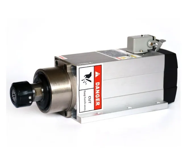
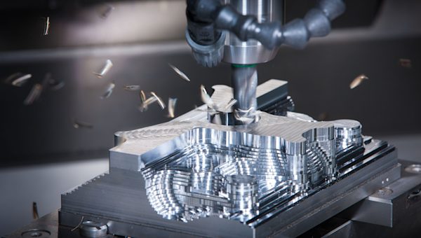
Image of a standard CNC milling spindle specifically designed for precision machining equipment
1.2 The Role of the Spindle Motor in Milling Machines
If we consider a milling machine as a complete organism, the spindle motor is its heart, pumping “blood” to power the entire system. It provides the direct driving energy for all cutting processes.
Regardless of how robust the mechanical system or how intelligent the controller is, they become meaningless without a spindle motor strong, stable, and precise enough to execute commands. The spindle’s speed, strength, and stability directly affect every aspect of machining.
1.3 Real-World Applications of Spindle Motors in Manufacturing
The spindle motor is the backbone of many industrial devices, including:
-
CNC Milling Machines: The most common application, used for mold making, machine parts, electronic components, and advertising products.
-
Conventional Milling & Turning Machines: Traditional versions also use motors to rotate the spindle.
-
CNC Engraving Machines: Dedicated to engraving and shaping on wood, stone, and non-ferrous metals with ultra-high-speed spindles.
-
Drilling and Boring Machines: Perform high-precision drilling and surface finishing.
-
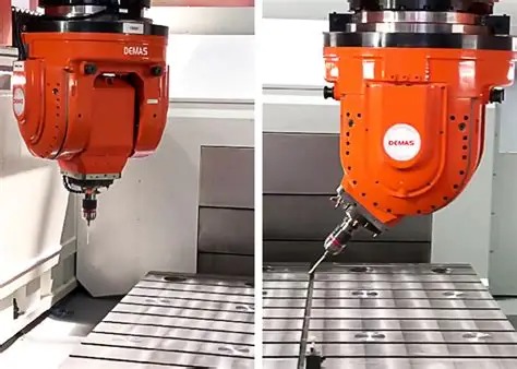
Industrial Robots: Many robotic arms are equipped with spindles for automated milling, grinding, or polishing.
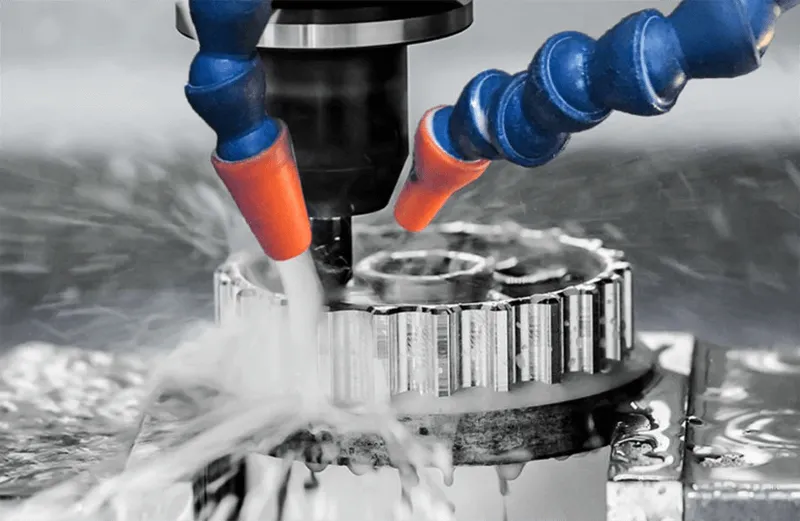
Applications of milling spindle in manufacturing
2. Structure and Working Principle of the Spindle Motor
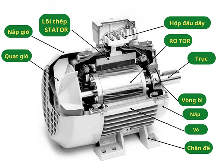
Schematic diagram showing the detailed internal structure of a CNC milling spindle, comprising rotor, stator, and bearings
2.1 Basic Components of a Spindle Motor
2.1.1 Stator
The stationary part of the motor, consisting of a laminated electrical steel core and copper windings. When AC current flows through, it generates a rotating magnetic field—the foundation of all motion.
2.1.2 Rotor
The rotating part, positioned concentrically inside the stator. The most common type is the squirrel-cage rotor, made of aluminum or copper bars embedded in slots and short-circuited at both ends. Under the influence of the stator’s rotating magnetic field, the rotor turns and drives the spindle shaft.
2.1.3 Bearings
Bearings are critical, determining spindle accuracy and lifespan. They support the rotating shaft, minimizing runout and vibration. High-end motors often use ceramic bearings for high-speed and high-temperature operation.

Close-up of a high-precision bearing inside a CNC milling spindle
2.1.4 Cooling System
Since spindle motors operate under high speed and heavy loads, they generate substantial heat. Cooling systems are essential to maintain safe operating temperatures:
-
Air-Cooled: Integrated fan blows air to dissipate heat.
-
Water-Cooled: Circulates coolant or water through internal channels.
2.2 Operating Principle in CNC and Conventional Milling Machines
In modern CNC machines, spindle motors primarily operate on the principle of a three-phase induction motor, controlled by a Variable Frequency Drive (VFD). The VFD alters input frequency, thereby precisely adjusting spindle speed.
In conventional milling machines, motors often run at fixed speeds. Spindle speed variation is achieved mechanically through belts (pulleys) or gearboxes.
3. Classification of Spindle Motors
3.1 By Voltage Type
-
AC Spindle Motors: The most common today, especially three-phase AC motors, offering high efficiency, durability, and easy speed control via VFD.
-
DC Spindle Motors: Less common in industrial milling spindles, mostly used in mini CNC or desktop machines requiring high starting torque at low speeds. Maintenance (brush replacement) can be more demanding.

A common 3-phase AC milling spindle model widely used in modern CNC machines
3.2 By Power Output
-
Low-Power Spindles (<2.2 kW): Suitable for light tasks such as engraving, softwood milling, plastics, acrylics, and thin aluminum sheets.
-
High-Power Spindles (≥3 kW): Capable of machining hard materials like steel, stainless steel, and titanium, supporting deep and fast cuts for heavy industries and mold-making.
3.3 By Control Technology
-
Standard Motors: Reliable asynchronous motors, sufficient for most machining tasks.
-
Servo Spindles: Advanced spindles with integrated encoders, providing precise angular position feedback. Essential for high-synchronization applications like rigid tapping or exact spindle orientation.

Actual image of a standard asynchronous milling spindle installed on a machine
4. The Role of Spindle Motors in Machining
4.1 Determining Spindle Speed (RPM)
Optimized speed improves surface finish and cutting efficiency.
4.2 Influencing Accuracy
Runout and vibration directly affect tolerances.
4.3 Impacting Tool and Product Life
A stable spindle extends tool lifespan and prevents breakage.
Comparison of tool life when using a stable vs. unstable milling spindle
4.4 Enhancing Productivity
Powerful spindles enable deeper cuts and higher feed rates without compromising quality.
5. Criteria for Selecting a Suitable Spindle Motor
5.1 Power Output
Match to material type (hard metals need higher power).
5.2 Speed Range
High speeds (18,000–24,000 RPM) for soft materials and fine engraving; lower speeds with higher torque for hard metals.
5.3 Compatibility
Ensure fitting dimensions, electrical connections, and VFD/system compatibility.
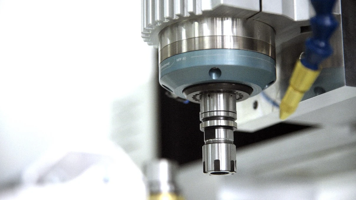
The selection of a milling spindle must ensure compatibility with the machine’s clamping system and control system
5.4 Efficiency & Stability
Choose energy-efficient, low-vibration, low-noise models.
5.5 Service & Spare Parts Availability
Prefer widely recognized brands for easy maintenance and support.
6. Installation and Operation Guidelines
6.1 Checking specifications before installation
Compare the motor’s voltage, frequency, and power with the inverter and factory power supply specifications to ensure compatibility.
6.2 Proper Mounting
Ensure flat, clean surfaces; tighten bolts evenly; connect cooling and electrical systems per manufacturer’s instructions.
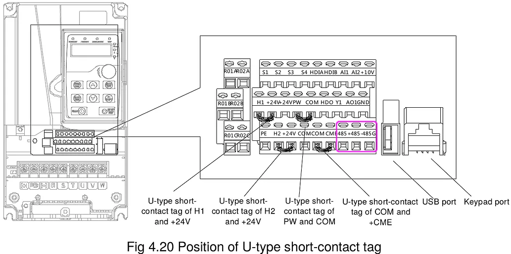
Installation procedure for mounting a milling spindle precisely onto the Z-axis of a CNC milling machine
6.3 Safe Operation
Always wear protective gear, secure workpieces, avoid loose clothing/jewelry.
6.4 Pre-Machining Check
Run spindle at various speeds without load to test stability, noise, and temperature.
7. Maintenance and Cleaning
7.1 Regular Cleaning
Remove chips, dust, and grease using compressed air and clean cloths.
7.2 Bearing Check
Listen for unusual noises indicating wear.
7.3 Monitor Heat & Noise
Stop immediately if overheating or abnormal sounds occur.
7.4 Timely Replacement
Replace worn parts (bearings, collets) promptly to prevent further damage.
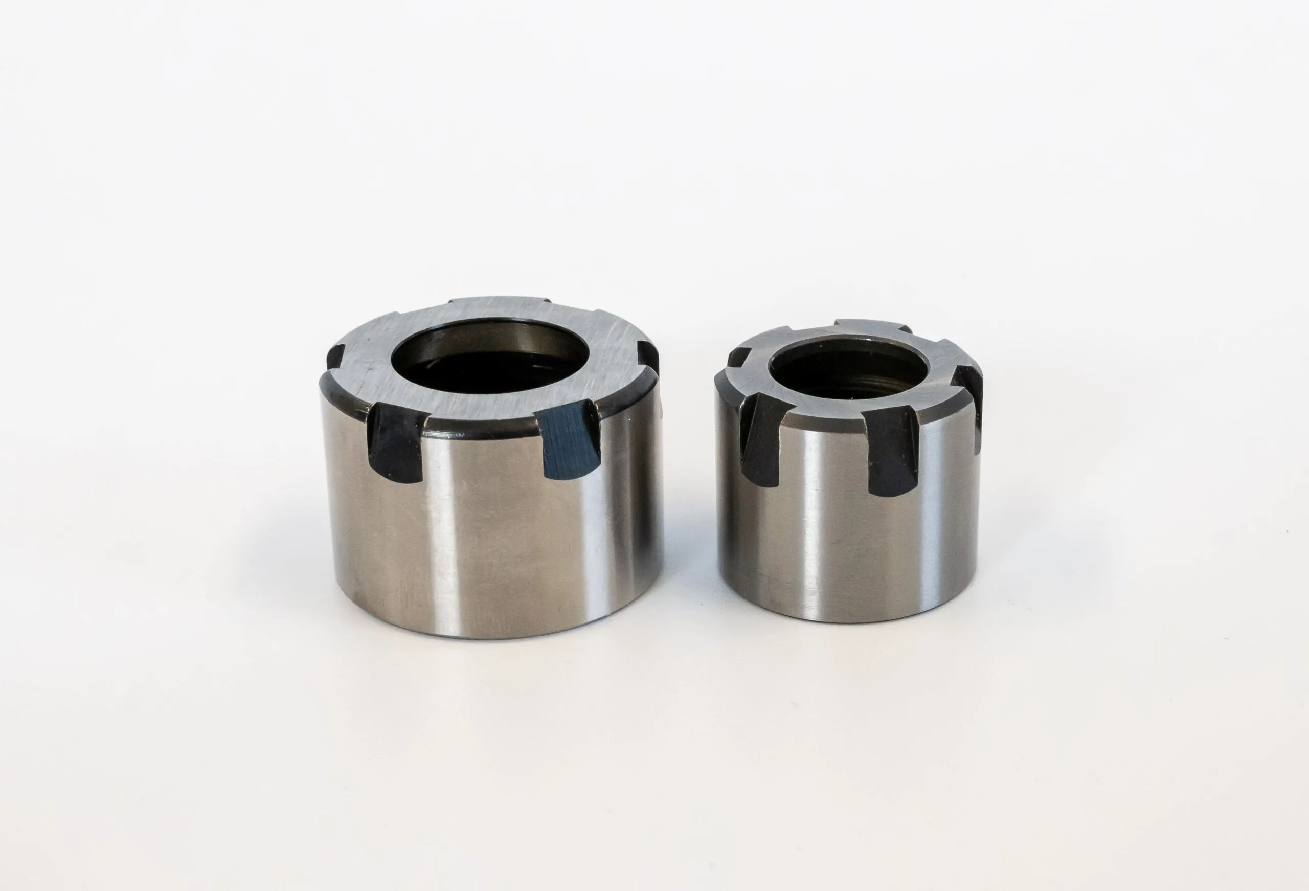
The importance of replacing milling spindle components once they show signs of wear
8. Common Issues and Troubleshooting
8.1 Motor Won’t Start
Check power supply, wiring, VFD error codes, coil resistance.
8.2 Excessive Noise
Caused by worn bearings, imbalance, or loose tool clamping.
8.3 Overheating
May result from overload, cooling failure, unstable voltage, or bearing friction.
8.4 Unstable Speed
Incorrect VFD settings, unstable power, or signal interference.
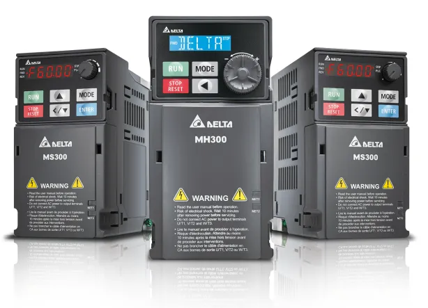
Troubleshooting methods for common milling spindle issues through inverter error code diagnostics
10. Trusted Supplier of Spindle Motors
Choosing a reliable supplier is as important as selecting the product itself. A professional supplier provides not only the motor but also peace of mind, technical support, and long-term efficiency.
Automech stands out as a supplier exceeding these criteria, delivering clear advantages:
-
Authenticity Guaranteed: Strategic partnerships with world-class spindle brands, full CO/CQ certification, eliminating counterfeit risks.
-
Expert Engineering Support: In-house engineers trained directly by manufacturers, providing tailored machining solutions.
-
Superior Warranty & After-Sales: Fast, professional warranty handling, with dedicated after-sales care to minimize downtime.
-
Readily Available Spare Parts: Stocked genuine bearings, collets, and components for immediate replacement.
-
Strategic Partnership Approach: Beyond sales, Automech positions itself as a long-term technical partner, helping clients enhance manufacturing capacity with the latest technologies.

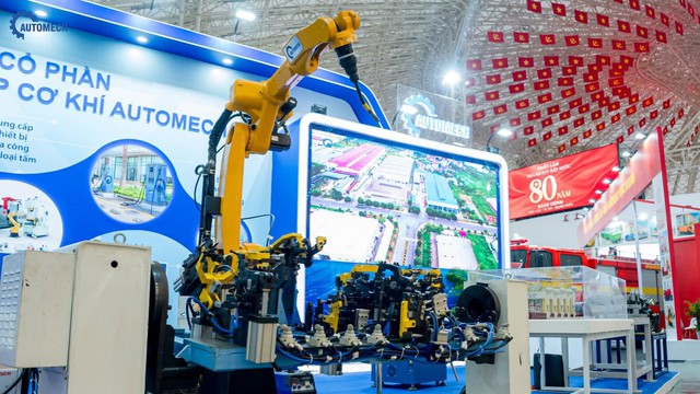
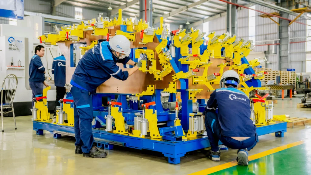
Automech is a trusted supplier of genuine CNC milling spindles and reliable automation solutions
Conclusion
Partnering with a professional supplier like Automech ensures not only genuine products but also a strategic investment in stability, performance, and long-term competitiveness for your business.
AUTOMECH MANUFACTURING AUTOMATION DIES AND TOOLS JSC
Address: Lot E5, Dinh Tram Industrial Park, Nenh Ward, Bac Ninh, Vietnam
Hotline: +84 907 89 89 62
Website: automechtool.vn
Fanpage: Automech Manufacturing Automation Dies and Tools JSC
YouTube: AutomechKhuonTools